What Is the Pin Reading Coming Out of a 17hs4401 Stepper Motor
A stepper motor is a blazon of DC motor that works in discrete steps and used everywhere from a surveillance camera to sophisticated robots and machines. Stepper motors provide authentic controlling, and can be differentiated on the footing of torque, steps per revolution, and input voltage. In our previous project, we controlled 28-BYJ48 stepper motor using Arduino. 28-BYJ48 has relatively lower torque than the other stepper motors similar NEMA fourteen, NEMA17.
In this tutorial, nosotros are going to command NEMA17 stepper motor using Arduino Uno and A4988 stepper driver module. Nema17 stepper motor has higher torque and higher operating voltage than 28-BYJ48. Here a potentiometer will too be attached to control the management of stepper motor.
Component Required
- Arduino UNO
- NEMA17 Stepper Motor
- A4988 Stepper Commuter Module
- 47 µf Capacitor
- Potentiometer
NEMA17 Stepper Motor

Functioning of Nema17 is similar to normal Stepper Motors. NEMA 17 stepper motor has a ane.vii x 1.7-inch faceplate, and it usually has more than torque than the smaller variants, such as NEMA xiv. This motor has half-dozen lead wires, and the rated voltage is 12 volt. It tin can be operated at a lower voltage, but torque volition drop. Stepper motors do not rotate they step, and NEMA17 motor has a step angle of ane.8 deg. means information technology covers ane.eight degrees in every step. Wiring diagram for NEMA17 is given below.

As you can come across that this motor has a Unipolar six-wire arrangement. These wire are connected in ii dissever windings. Blackness, Yellowish, Green wires are part of first winding where Blackness is center tap, and Yellowish and Green are coil finish while Ruddy, White, and Bluish is part of a second winding, in which White is center tap and Ruby-red and Blueish are coil end wires. Normally center tap wires left asunder.
Steps Per Revolution for NEMA17
Steps Per Revolution for a particular stepper motor is calculated using the pace bending of that stepper motor. So in the case, NEMA 17 step angle is 1.eight deg.
Steps per Revolution = 360/ step angle 360/1.8 = 200 Steps Per Revolution
Specifications of NEMA17
- Rated Voltage: 12V DC
- Step Angle: i.8 deg.
- No. of Phases: 4
- Motor Length: 1.54 inches
- 4-wire, 8-inch pb
- 200 steps per revolution, 1.8 degrees
- Operating Temperature: -x to twoscore °C
- Unipolar Belongings Torque: 22.2 oz-in
Also check various stepper motor related projects hither, which not only incudes basic interfacing with various microcontrollers but also accept robotics projects which involves stepper motor.
A4988 Stepper Commuter Module
A stepper commuter module controls the working of a stepper motor. Stepper drivers ship the current to stepper motor through diverse phases.
The A4988 Nema 17 stepper driver is a microstepping driver module that is used to control bipolar stepper motors. This driver module has a built-in translator that ways that we can control the stepper motor using very few pins from our controller.

Using this Nema 17 motor driver module, we tin control stepper motor by using only two pins, i.e., Step and DIRECTION. STEP pin is used to control the steps while DIRECTION pin is used to command the management of the motor. A4988 driver module provides v different step resolutions: full-step, haft-step, quarter-step, viii-step, and sixteenth-step. You tin can select the different step resolutions using the resolution selector pins ((MS1, MS2, and MS3). The truth table for these pins is given below:
| MS1 | MS2 | MS3 | Microstep Resolution |
| Low | Low | Low | Full Step |
| High | Depression | Low | ½ Step (Half Step) |
| Low | Loftier | Low | ¼ Pace (Quarter Stride) |
| High | High | Depression | i/8 Step (Eighth Footstep) |
| High | High | Loftier | 1/sixteen Stride (Sixteenth Pace) |
Specifications of A4988
Max. Operating Voltage: 35V
Min. Operating Voltage: 8V
Max. Electric current Per Phase: 2A
Microstep resolution: Full step, ½ footstep, ¼ pace, ane/8 and 1/16 footstep
Reverse voltage protection: No
Dimensions: 15.5 × 20.5 mm (0.half dozen″ × 0.viii″)
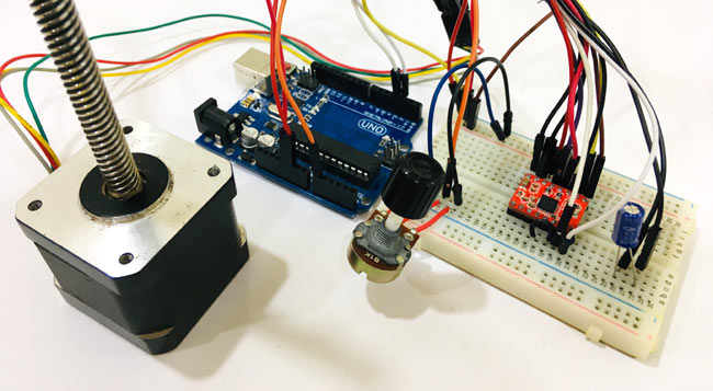
Excursion Diagram

Circuit diagram to controlNema 17 stepper motor with Arduino is given in the above epitome. As A4988 module has a built-in translator that means we simply need to connect the Footstep and Direction pins to Arduino. Step pivot is used for controlling the steps while the direction pin is used to control the direction. Stepper motor is powered using a 12V ability source, and the A4988 module is powered via Arduino. Potentiometer is used to control the direction of the motor.
If you lot turn the potentiometer clockwise, so stepper will rotate clockwise, and if you turn potentiometer anticlockwise, then it will rotate anticlockwise. A 47 µf capacitor is used to protect the lath from voltage spikes. MS1, MS2, and MS3 pins left asunder, that means the commuter will operate in full-pace mode.
Complete connections forArduino Nema 17 A4988 given in below tabular array.
| S.NO. | A4988 Pivot | Connectedness |
| ane | VMOT | +ve Of Battery |
| 2 | GND | -ve of Battery |
| 3 | VDD | 5V of Arduino |
| iv | GND | GND of Arduino |
| v | STP | Pivot 3 of Arduino |
| six | DIR | Pin 2 of Arduino |
| 7 | 1A, 1B, 2A, 2B | Stepper Motor |
Code Explanation
Complete code with working videocontrol Nema 17 with Arduino is given at the end of this tutorial, hither nosotros are explaining the consummate program to sympathize the working of the projection.
First of all, add the stepper motor library to your Arduino IDE. You can download the stepper motor library from hither.
After that define the no of steps for the NEMA 17. As we calculated, the no. of steps per revolution for NEMA 17 is 200.
#include <Stepper.h> #define STEPS 200
After that, specify the pins to which commuter module is connected and define the motor interface type equally Type1 because the motor is connected through the driver module.
Stepper stepper(STEPS, 2, 3); #define motorInterfaceType 1
Next set the speed for stepper motor using stepper.setSpeed function. Maximum motor speed for NEMA 17 is 4688 RPM but if we run it faster than m RPM torque falls of apace.
void setup() { stepper.setSpeed(chiliad); Now in the main loop, we will read the potentiometer value from A0 pivot. In this loop, at that place are two functions one is potVal, and the other is Pval. If the electric current value, i.e., potVal is higher than the previous value, i.eastward., Pval than it will move 10 steps in the clockwise direction and if the electric current value is less than previous value than it will move ten steps in the counter-clockwise direction.
potVal = map(analogRead(A0),0,1024,0,500); if (potVal>Pval) stepper.step(ten); if (potVal<Pval) stepper.step(-10); Pval = potVal;
Now connect the Arduino with your laptop and upload the code into your Arduino UNO board using Arduino IDE, select the Board and port no and then click on the upload button.
Now you tin command the direction of Nema17 stepper motor using the potentiometer. The complete working of the project is shown in the video below. If you have whatever doubts regarding this project, mail service them in the comment section below.
Code
#include <Stepper.h>
#define STEPS 200
// Define stepper motor connections and motor interface blazon. Motor interface type must be set to 1 when using a driver
Stepper stepper(STEPS, 2, 3); // Pin 2 connected to DIRECTION & Pin three continued to Step Pin of Driver
#ascertain motorInterfaceType 1
int Pval = 0;
int potVal = 0;
void setup() {
// Gear up the maximum speed in steps per second:
stepper.setSpeed(1000);
}
void loop() {
potVal = map(analogRead(A0),0,1024,0,500);
if (potVal>Pval)
stepper.footstep(10);
if (potVal<Pval)
stepper.step(-10);
Source: https://circuitdigest.com/microcontroller-projects/controlling-nema-17-stepper-motor-with-arduino-and-a4988-stepper-driver-module
0 Response to "What Is the Pin Reading Coming Out of a 17hs4401 Stepper Motor"
Post a Comment